
An Accessible Seeded Field for Humanitarian Mine Action Research
By Jasper Baur,* *** Gabriel Steinberg,* John Frucci, PhD,** and Anthony Brinkley* [*Demining Research Community, **Oklahoma State University, ***Lamont-Doherty Earth Observatory at Columbia University ]
CISR Journal
This article is brought to you by the Center for International Stabilization and Recovery (CISR) from issue 27.3 of The Journal of Conventional Weapons Destruction available on the JMU Scholarly Commons and Issuu.com.
The detection of buried and surface explosive remnants of war (ERW) is a critical task in the land release process.1 The goal of this project is to create a long-term study site and benchmark to accelerate humanitarian mine action (HMA) research for the detection of buried ERW, including unexploded ordnance (UXO), landmines, and improvised explosive devices (IEDs). A crucial step in transitioning experimental detection techniques from the lab to the field is conducting rigorous field testing in a realistic and safe environment.2,3,4 With most academic institutions lacking access to stockpiles of inert ERW to conduct testing and prioritizing scientific publications over real-world field applicability, this step is too often neglected. The result is that most HMA studies lack sufficient benchmarking among detection variables such as depth of burial, size and diversity of ERW, and environmental context, making it nearly impossible to objectively compare the effectiveness of different instruments and sensors. Consequently, the humanitarian demining community is less willing to accept novel methods and instead relies largely on traditional approaches.
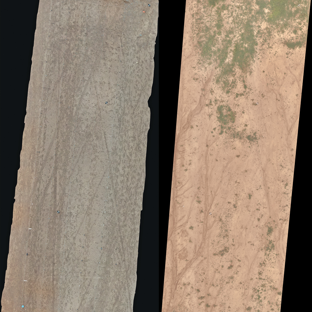
Figure 1. Orthomosaic of the initial field on 7 March 2023 (LEFT) next to the same field on 13 June 2023 (RIGHT) processed in Pix4DMapper. All graphics courtesy of the authors.
Military munitions response (MMR), an industry focused on clearing UXO from formerly used defense sites, differs from HMA in that it has strict industry standards and protocols for testing and evaluating new instruments and methods on ground-truthed seeded fields with known geophysical signatures and depths of burial.5 Unfortunately, access to these fields are restricted and the results of the benchmark tests are rarely released to the scientific community. Additionally, MMR focuses almost exclusively on larger, buried metal UXO, while HMA deals with clearance of landmines, UXO, and IEDs which can include plastic or low-metal content objects that are present on the surface and at depth.6
Overview
To address this issue, the Demining Research Community,7 (a US-based nonprofit organization whose mission is to advance the field of HMA though bridging academic research in accordance with demining organizations), in partnership with the Global Consortium for Explosive Hazard Mitigation at Oklahoma State University (OSU), have seeded a comprehensive field with 143 diverse items including landmines, submunitions, UXO, and IEDs located at OSU’s Center for Fire and Explosives, Forensic Investigation, Training and Research (CENFEX) range in Pawnee, Oklahoma. This field was initially seeded in March 2023 and was reseeded at a permanent location in June 2023. The permanent site will be open to the broader mine action community to test equipment and methods for detecting and mapping ERW.
Initial Test Site
Environment. The topsoil of the burial site is a silt loam for the A horizon 0–18 cm and a silty-clay loam 18–30 cm for the Bt1 horizon. It is categorized dominantly as a RenC2-Renfrow silt loam by the Web Soil Survey (WSS) from the US Department of Agriculture.8 The field is oriented approximately north-south in the long direction. It is located on an explosive test range and is therefore littered with small metal fragmentation. The field is relatively flat with no strong gradients that were visually apparent. There was no vegetation at the time of burial 7 March 2023, but after three months, knee-height weeds in the northern end of the field grew (Figure 1). We can expect vegetation growth as time passes depending on the time of year.
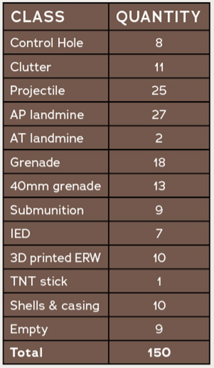
Burial grid. We buried 143 items in total (including control holes) in a grid pattern that covered 10 x 40 m for an area of 400 m2. The grid consists of six columns (labeled A–F) spaced 2 m apart, each with 25 rows (labeled 1–25) spaced 1.5 m apart (Figure 2). We placed six ground control points (GCPs), one at each corner and two inside of the grid. The Northwest corner of the grid is A1 with the southeast corner being F25. The buried items are a diverse set of ERW. We categorize each item into broad classes consisting of Control hole, Clutter, Projectile, Anti-personnel (AP) mine, Anti-tank (AT) mine, Hand grenade, 40mm grenade, Submunition, Improvised Explosive Device (IED), 3D printed ERW, Shells & Casings, and Empty (nothing buried in this location). The quantity of each class is shown in Table 1 and the specific type of ERW along with its weight, size, ferrous or nonferrous metal content, and related notes are available in Table 4. The items were buried organized into columns by class and in some cases physical properties and appearance.
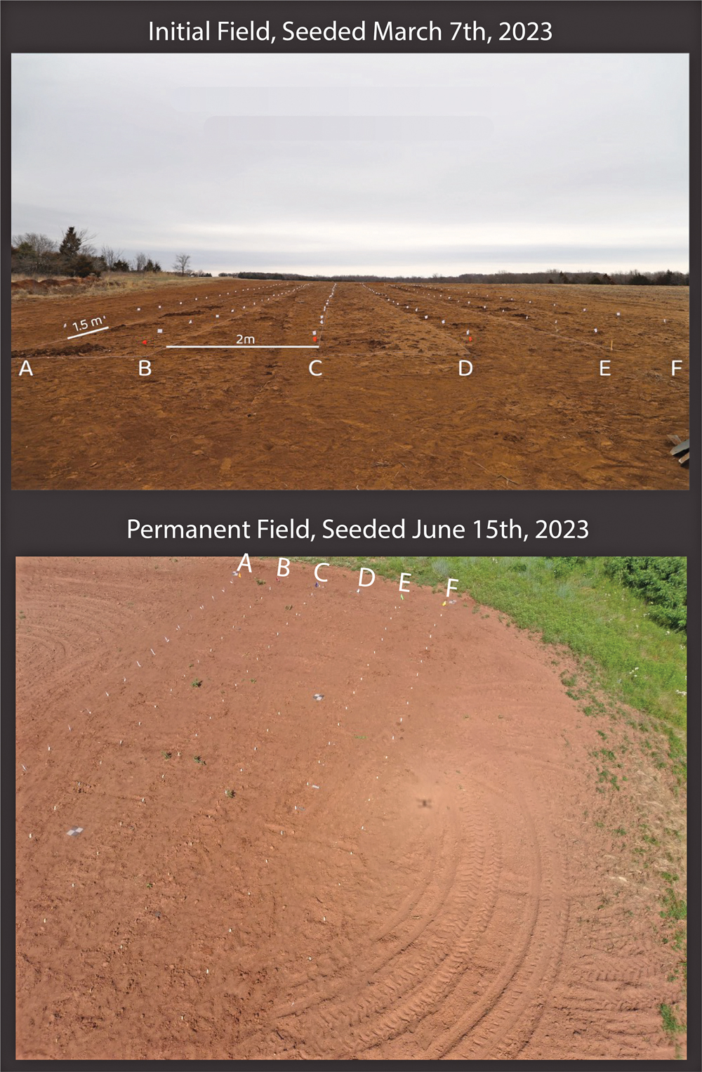
Figure 2. Top panel shows an oblique angle of the initial field oriented from south (bottom) to north (top) showing columns A–F. Bottom panel shows an oblique angle of the permanent field oriented from east (bottom) to west (top) showing columns A–F.
Figure 3 shows all the items in a condensed grid for visualization purposes. Column A contained six larger metal projectiles, one AT mine, and six IEDs, with smaller 3D-printed ERW and empty spaces placed between the larger metal items to minimize magnetic interference between objects during data acquisition. Column B contains eighteen hand grenades, one landmine, and six projectiles. Column C contains thirteen 40mm grenades, three projectiles, and nine submunitions. Column D contains only AP mines. Column E contains thirteen projectiles, one landmine, ten shells or casings, and two IEDs. Column F contains two munition cases, one filled with fuzes and the other with shrapnel, one plastic AT mine, and ten pieces of clutter that include cell phones, a copper pipe, aluminum cans, and metal shrapnel.
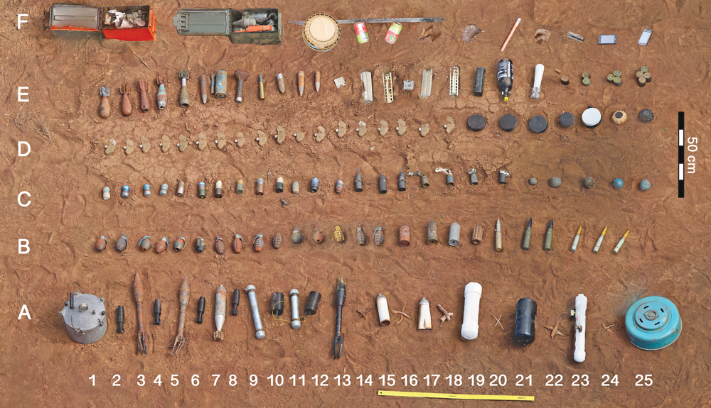
Figure 3. Condensed grid for visualization of placement of each item, produced from structure-from-motion photogrammetry. Columns A–E are accurate in terms of placement and order in the buried grid, and F is accurate in order of items, but there is offset of item placement. The exact placement and corresponding names of the items are available in Tables 2 and 4.
Experimental Design
The diversity of ERW and the structure of the field was designed to allow scientists and researchers to tackle numerous questions related to ERW detection. This involves deciphering which sensors are most useful for detection of which types of ERW.9 Each grouping of items as described previously were buried at different depth intervals to explore how different geophysical signatures of the ERW attenuate with depth. The depth for each item was carefully determined based on the likely field deployment and depth of penetration for the specific ERW. Larger projectiles are prone to penetrate deeper into the ground, whereas submunitions and scatterable landmines are placed on the surface and may become shallowly buried with time.10 For example, in B1–B5, five nearly identical hand grenades were placed at different depths: one placed on the surface, one at 2 cm, 4 cm, 6 cm, and 8 cm respectively. Grenades are likely to be found on or close to the surface, so they were buried at shallow depths in increments of 2 cm up to a final depth of 8 cm. This will allow researchers to examine the signal attenuation with depth for future thermal, magnetic, and ground penetrating radar (GPR) surveys.
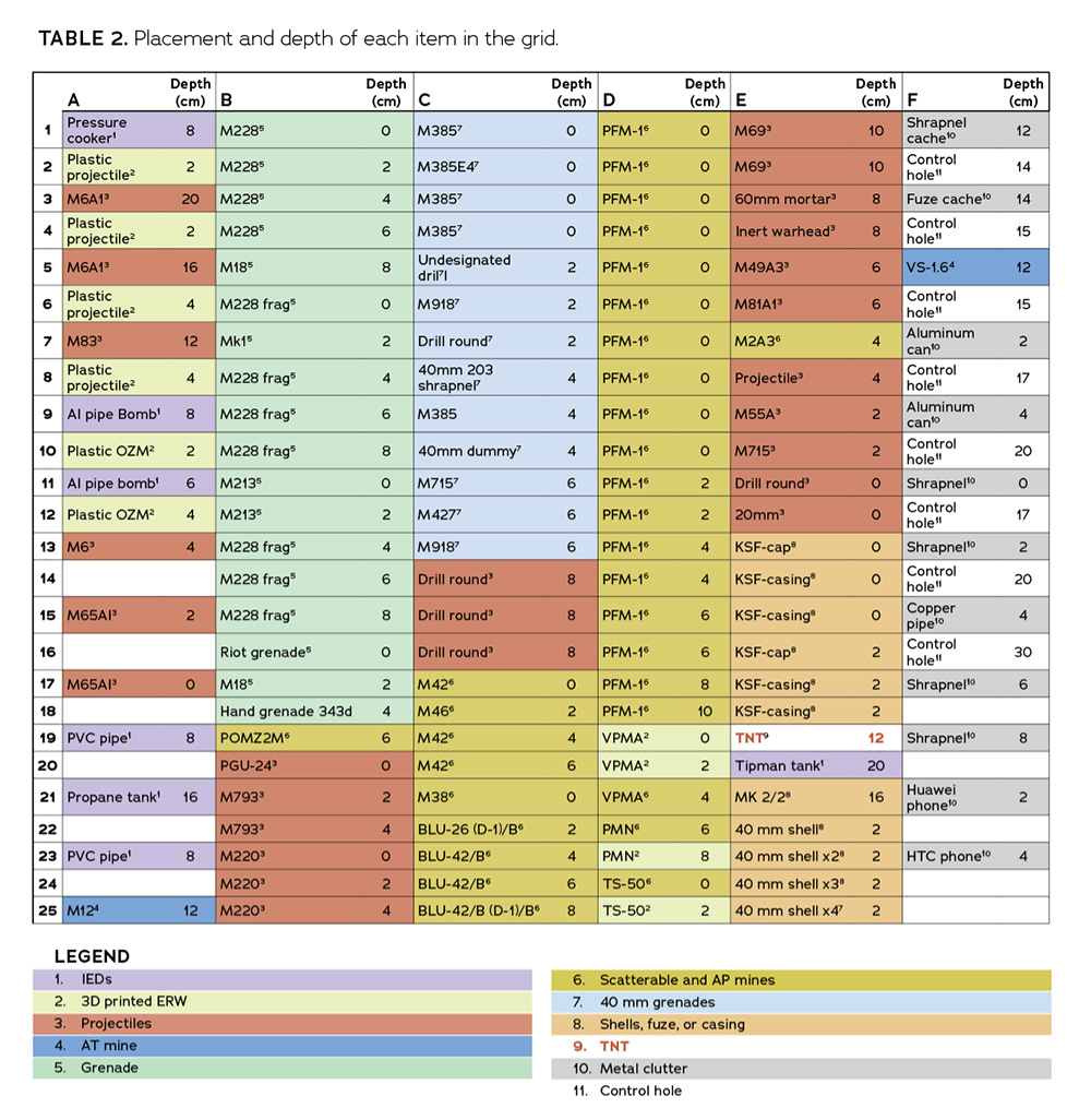
The burial depths ranged from the surface to 20 cm. Tables 2 and 4 have all the depth information per item. Additionally, control holes were dug at various depths and filled with the goal of decoupling a signature resulting from soil displacement or disturbance from one resulting from the items themselves. This may be especially relevant for LiDAR and depth sensors that look at soil subsidence.11 Similarly, the clutter items will help determine if the signatures of the ERW are unique and if they can be distinguished from metal and electronic clutter. The non-unique signature problem is particularly difficult for certain sensor modalities, and we hope that the presence of clutter in our seeded field will help researchers identify ways to reduce false positive detections.12,13
There are plastic, low metal, and metal (ferrous and non-ferrous) ERW buried in the seeded field. This will allow researchers to compare the viability of different sensor modalities for different material properties. For example, we have the metal American M-12A1 anti-vehicle (AV) landmine and the plastic Italian VS-1.6 AV landmine both buried at 12 cm depth.
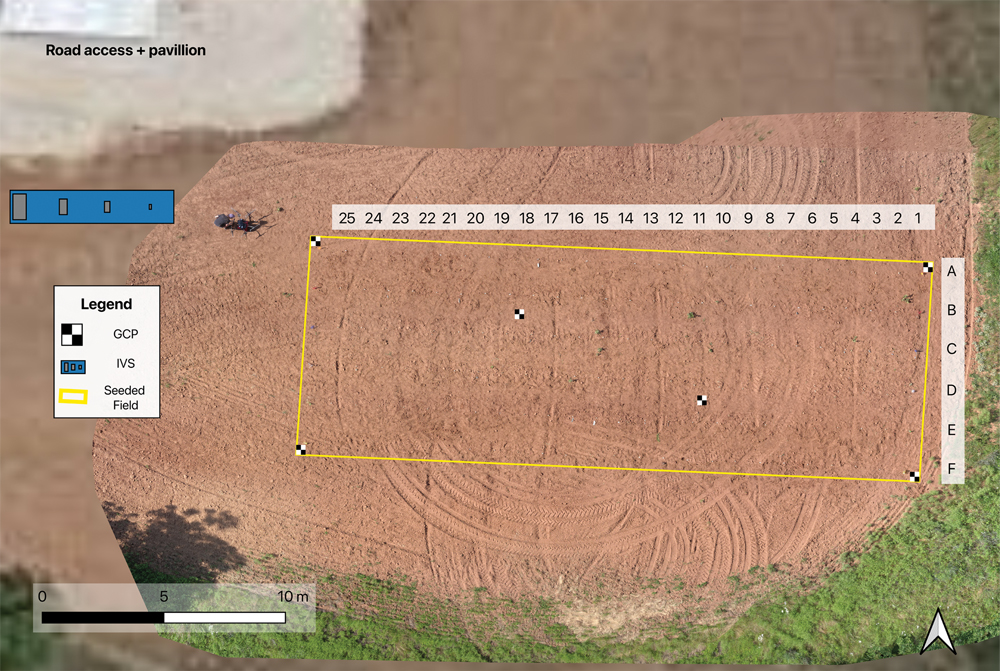
Figure 4. Permanent seeded field map displayed as an orthomosaic on a satellite map. The blue square shows the location of the IVS relative to the field. There is a pavilion for field operation logistics and gravel road access to the site.
Over time (months to years), natural environmental emplacement and equilibriums will be reached, providing us with a realistic field that is usually only found in confirmed hazardous areas. This time-since-seeded variable is often unaccounted for in other HMA geophysical studies and is especially relevant for datasets that rely on realistic resettling of the ground or a thermal equilibrium to be reached.14,15,16,17 Lastly, while weeds and light vegetation are present, there are no large trees or bushes in the field site to prevent testing of unmanned aerial vehicles (UAVs) and ground-based methods.
Limitations
Given one test location, studies using this field cannot address the effect of differing environmental factors such as soil type and vegetation biodiversity on detectability of ERW. Landmines and UXO are found in sixty countries and territories around the world in diverse environments ranging from the tropical rainforests of Southeast Asia to the deserts of the Sahara, thus not all the geophysical tests on this field will provide transferable knowledge for ERW detectability in all regions of the world.18 Despite this, it is necessary to constrain environmental variables to allow for a clear, objective comparison of detection rates for different geophysical sensors. Other environmental parameters such as soil moisture, temperature, and humidity, which affect GPR and thermal imagery, change daily and must be considered and recorded.19,20
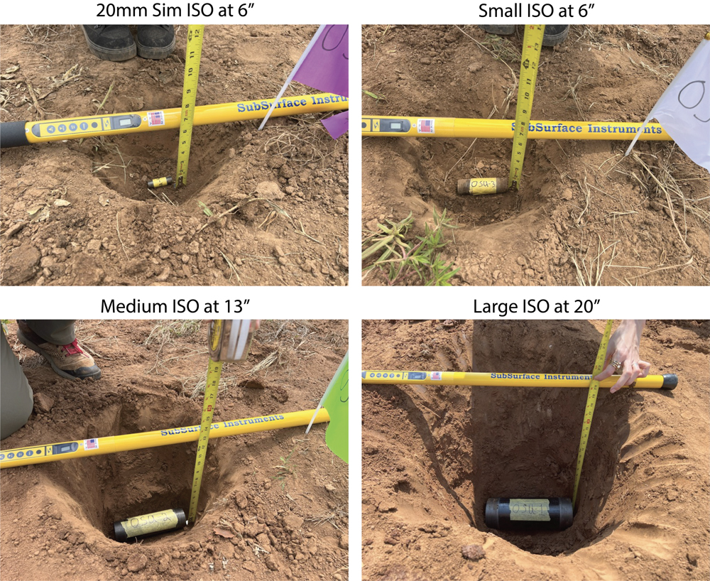
Figure 5. Instrument verification strip, ISO buried at recorded depths of 6 inches (15.2 cm), 13 inches (33.0 cm), and 20 inches (50.8 cm) respectively.
Benchmark Surveys
From 12–16 June 2023, the Demining Research Community with affiliate researchers from OSU, the Department of Geological Sciences at Binghamton University and University of Maryland, and Lamont-Doherty Earth Observatory at Columbia University collected the first major datasets on the seeded field. Among the datasets collected were thermal, visual, magnetic, GPR, stereoscopic, and LiDAR surveys with both UAV- and ground-based platforms (cart and handheld) over the field site. Once processed, these datasets and the subsequent analysis will be made freely available to the HMA community, providing the first comparative dataset on this seeded field for future studies.
Permanent Site
On 15 June 2023, after the benchmark surveys on the initial field were conducted, the items were unburied and reseeded in a new permanent site. The ongoing burial is meant to simulate real-world conditions where UXO and mines need to be detected months to years after a conflict has ended.
The permanent site has the same seeding pattern and burial depths as the original field. The primary difference is that the twenty-five rows are spaced 1 m apart instead of 1.5 m in the previous field due to a space constraint. The dimensions of this field are 10 m x 25 m with a total area of 250 m2 (Figure 4). This field is about 150 m from the initial site and oriented approximately east-west lengthwise. The soil layers vary slightly from the initial field with the first 6–8 cm consisting of silty loam and 8–30 cm depth consisting of a dense silty-clay that is difficult to dig through. Wooden popsicle sticks were placed to mark the locations of the buried items so as not to interfere with future magnetic surveys. There is a minimal amount of small metal fragmentation in this site compared to the initial site.
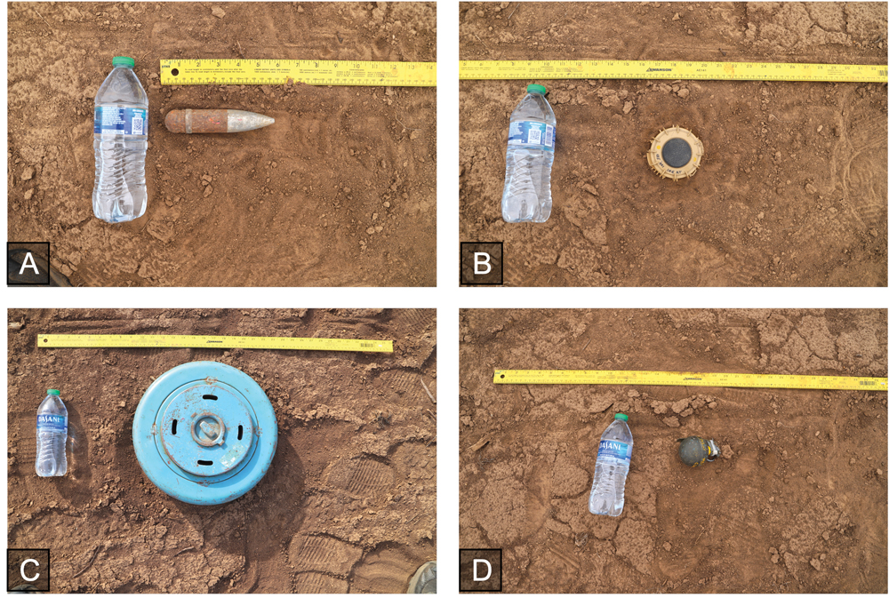
Figure 6. Scaled pictures of A) 20mm projectile, B) TS-50 AP mine, C) M12 AT mine, D) M213 grenade.
|
GCP/ISO |
LATITUDE |
LONGITUDE |
|
GCP NE |
36.3531001 |
-96.856893 |
|
GCP NW |
36.3531111 |
-96.857171 |
|
GCP SE |
36.3530033 |
-96.8569 |
|
GCP SW |
36.3530164 |
-96.857078 |
|
GCP NW-center |
36.3530772 |
-96.857078 |
|
GCP SE-center |
36.3530375 |
-96.856996 |
|
ISO 20mm |
36.3531296 |
-96.857243 |
|
ISO small |
36.3531282 |
-96.857263 |
|
ISO medium |
36.3531299 |
-96.857285 |
|
ISO large |
36.3531283 |
-96.857306 |
An instrument verification strip (IVS) was installed near the permanent site. The IVS has items with known shapes, sizes, and magnetic signatures that serve to calibrate instruments, especially magnetometers. The IVS contains four industry standard objects (ISO) 3 m apart as shown in Figure 4 to include two small, one medium, and one large ISO (Figure 5). The two small ISOs were buried horizontally at 6 inches, the medium ISO was buried horizontally at 13 inches, and the large ISO was buried horizontally at 20 inches. Each ISO was made from black steel pipe nipples, with the exception of one small ISO. The first small ISO is a heavy hex head bolt, 2 inches long. The second small ISO is Schedule 40, 1 inch straight pipe nipple and is 4 inches long. The medium ISO is Schedule 40, 2 inch straight pipe nipple and is 8 inches long. The large ISO is a Schedule 40, 4 inch straight pipe nipple and is 12 inches long.
Six ground control points (GCPs) were placed at the permanent site: one at each corner of the grid and two in the center. The NW-center GCP is located between columns B and C and rows 16 and 17 and the SE-center GCP is located between columns D and E and rows 8 and 9. The placement of each ISO and GCP was recorded using a handheld Trimble Geo7x with accuracy of ±5 cm. Coordinates of the GCPs and ISOs are provided in Table 3.
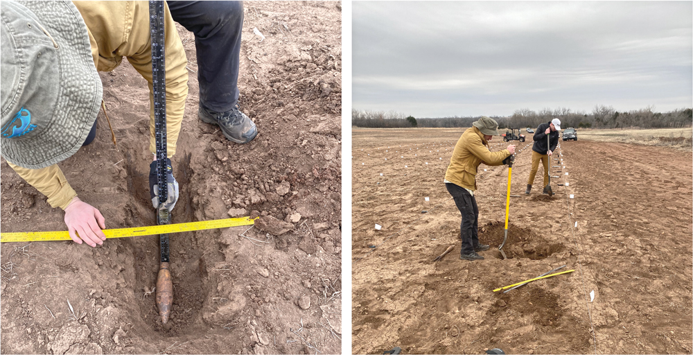
Figure 7. The left image shows the technique used to measure burial depth. The right image shows the digging process.
Methods
Pre-burial data collection. Prior to burial, each item was weighed, measured (length and diameter), photographed with and without a scale, and underwent a ferrous metal test. The workflow for taking these measurements followed a systematic process. First, we organized the ERW into a condensed grid in the arrangement in which they would be buried (Figure 3). Next, each item was weighed on a small food scale accurate to 1 g. A small portion of the larger items (such as the pressure-cooker and metal AT mine) were too heavy for the small scale and were weighed using a digital luggage scale accurate to 100 g. Next, we used a ruler to measure the length and diameter of each item in place. Then we conducted a ferrous metal test, placing a magnet on each item and recording if the item was composed of a ferrous or non-ferrous material. Finally, we placed the items next to a water bottle and a ruler for scale and took bird’s eye view pictures. Figure 6 shows examples of the scaled pictures. The collected data for each item can be found in Table 4. These measurements were collected prior to seeding the initial test site.
Burial techniques. After each item went through several measurements, we transported them to their designated burial location. After all the items were placed, we conducted a thermal and visual light drone survey over the field. The processed visual surveys are shown in Figures 1 and 4. Next, we dug burial holes for each item and placed the item into its hole. We tried to dig holes to the proper depth to mitigate soil disturbance. In some instances, the hole was deeper than intended and we had to remove the item, infill it, and then replace the item. In other instances, we needed to continue digging to make the hole the intended depth. After the item was placed into the hole, two rulers were placed, one horizontal on the soil surface and one vertical resting on the uppermost surface of the item. We then recorded the depth to the center of mass of the object based on the intersection of these rulers (Figure 7). For this method, we estimate an error of ±1 cm. Once an item was buried, the hole would be filled until level with the surface and the soil was not manually compacted.
Conclusion
We seeded a well-documented test field consisting of 143 diverse inert ERW in a grid pattern at depths ranging from 0 to 20 cm equipped with an instrument verification strip. This field is intended to serve as a benchmark to the HMA community, allowing researchers to thoroughly test the methods and instruments they develop with transparency and uniformity. The first iteration of this field was seeded on 7 March 2023 and remained in place for three months. Before the initial site was unburied, our team along with university and industry partners, collected the first aerial and ground-based magnetic, GPR, thermal, visual, and LiDAR surveys that will serve as the baseline datasets for this field. The same field of 143 items was reseeded at a nearby location on 15 June 2023 at a permanent site. To our knowledge, this is the most diverse field of inert munitions seeded for HMA testing purposes. This resource will help bridge the gap between academia and HMA by offering researchers a realistic field to assess ERW detection methods and HMA operators a framework through which to compare them.
Acknowledgements
A big thank you to Billy Magalasi and Greg Powers who manage the CENFEX range and greatly facilitated operations for this project. We want to thank Alex Nikulin and Tim de Smet for donating the PFM-1s to this field. We also thank Heidi Meyers, Cole Petrich, Gabriel Chen, Ved Lekic, Meyer Taffel, and Alex Pick-Aluas who assisted in the unburial and reburial process for this fieldwork.
 Jasper Baur is the co-founder and President of the non-profit organization Demining Research Community and the Lead Scientist at Safe Pro AI. Baur is a PhD candidate at Columbia University studying remote sensing applied to explosive hazard mitigation ranging from detecting small anti-personnel landmines to monitoring Alaskan volcanoes. He graduated from Binghamton University in 2020 with a Bachelor of Science in Geological Sciences, and a master’s from Columbia University in 2022 in physical volcanology. He has received numerous awards for his work in landmine detection and is always striving to innovate in the humanitarian mine action space. He is an FAA 107 certified UAS remote pilot and has months of fieldwork experience in remote environments.
 Gabriel Steinberg is the co-founder, Lead Software, and AI Engineer at Safe Pro AI and co-founder and Vice President of the non-profit organization Demining Research Community. Steinberg completed his Bachelor of Science in Computer Science at Binghamton University and studied toward his Master of Science in Computer Science at Karlsruhe Institute for Technology with a concentration in artificial intelligence. His main research interest is in computer vision with the goal of detecting scatterable landmines and unexploded ordnance from unmanned aerial vehicles. He has published and presented his research in several journals and at conferences, and worked in state-of-the-art AI research teams focusing on data science and machine learning applications in bioinformatics, passive bioacoustic monitoring, and large-scale software agent simulations.
 John Frucci, PhD, has been at OSU in the School of Forensic Sciences for eleven years. He is the Program Director of the Arson, Explosive, Firearms and Tool Marks Investigation, and the Forensic Investigative Sciences graduate programs. Frucci is the Director of the Center for Fire & Explosives, Forensic Investigations Training & Research and the OSU Global Consortium for Explosive Hazard Mitigation. Frucci was a career law enforcement officer for the Essex County Sheriff’s Office in Newark, New Jersey, serving in several units including as an FBI Certified Bomb Technician and Commander of the Bomb Squad. He retired in 2013. He earned his bachelor’s degree in 1997 from Rutgers University, his master’s degree in 2000, and his education specialist degree in education administration and supervision in 2006 from Seton Hall University. He earned his PhD in May 2018 at OSU and completed an additional master’s degree from the Missouri University of Science and Technology in Explosives Engineering and Technology in 2020.
 For the past three years, Anthony Brinkley has been associated with Oklahoma State University, School of Forensic Sciences. Having earned his Master of Science in Forensic Sciences from OSU in spring of 2023, he is currently pursuing a PhD in the same field. Brinkley has over thirty-five years of experience with UXO beginning in the US Navy, where he served for twenty-five years in roles such as Salvage Diver, Salvage Diving Officer, and Special Operations/EOD Officer. Since retiring from the US Navy in 2013, Brinkley has remained committed to the EOD community overseeing and conducting numerous munitions and explosives removal projects. Currently, he serves as Vice President of Pacific Rim Services, Guam LLC, where he plays a crucial role in supporting the US Marine Corps buildup in the Pacific region. In addition, he provides UXO support for Ukraine.
| Stay updated | |||